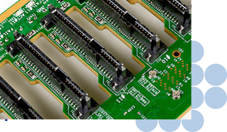
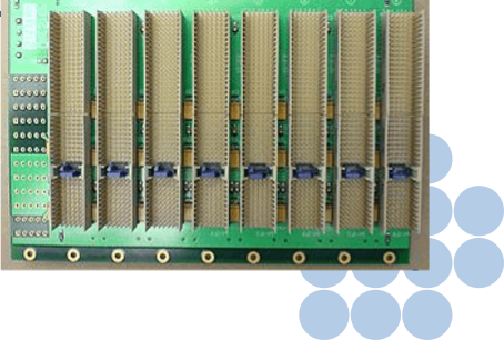
VME 64X Backplane
The VME64x is an extension of the VME family according to ANSI/VITA 1.1-1997 and permits 64-bit data traffic. This system is downward compatible, so that assemblies with 96-pin connectors to DIN 41612 can be inserted in the 160-pin socket connectors on the backplane.
Following Options are Available
1
Manual Daisy Chaining
In the case of unused slots, the daisy chain signals can be bridged by means of jumpers or wire-wrap connections from the front or rear of the backplane. Power is supplied via screw connections and terminal bars.
2
Automatic Daisy Chaining
Automatic daisy chain wiring with OR gates makes manual setting of jumpers unnecessary.
3
Live Insertion and Automatic Daisy Chain
Live Insertion does not require additional modules; these have already been integrated in the backplane. Automatic daisy chain wiring with OR gates makes manual setting of jumpers unnecessary.
CPCI Backplanes:
General and technical Information
The CompactPCI bus is compatible with the PCI bus known from the PC world as far as the electrical specifications are concerned. The mechanical specifications were adapted to the commonly used Euro-board plug-in system in the 19? card rack. Therefore this bus is also suitable for industrial purposes. Previously unattained signal speeds supported by the layout technology developed by Guarantee more stability and reliability for assemblies operating in the limit range. The backplanes are distinguished by a completely novel energy buffering feature which works across the entire frequency range. This feature guarantees improved reliability thanks to more stable supply voltages directly at the slot in conjunction with fluctuating loads.
Chassis GND connection
A continuous electrically conductive chassis GND surface is located in the area where the bus board is mounted on the card rack. An M3 screw connection is available to connect the chassis ground. By installing a connecting bracket or terminal bar, the chassis GND can be connected to GND in a low-resistance star arrangement.
JTAG connector
A separate 6-pin connector for JTAG boundary scan is implemented on the backplane.
Faster, simpler system initialization and testing by means of the JTAG bus even in the completely mounted state are achieved by direct access via an additional connector on the backplane.
Utility connector
The special signals to the power supply unit and external LEDs are routed to separate plug-in connectors on the backplanes. Depending on the backplane type, either a 10-pin or a 14-pin connector is used.
ATX connector
The ATX power supply connector used in the PC world is integrated in some backplane variants.
This results in a highly efficient and economic solution for supplying power to the backplane via ATX connectors and for the wiring of fans and drives.